Drive train
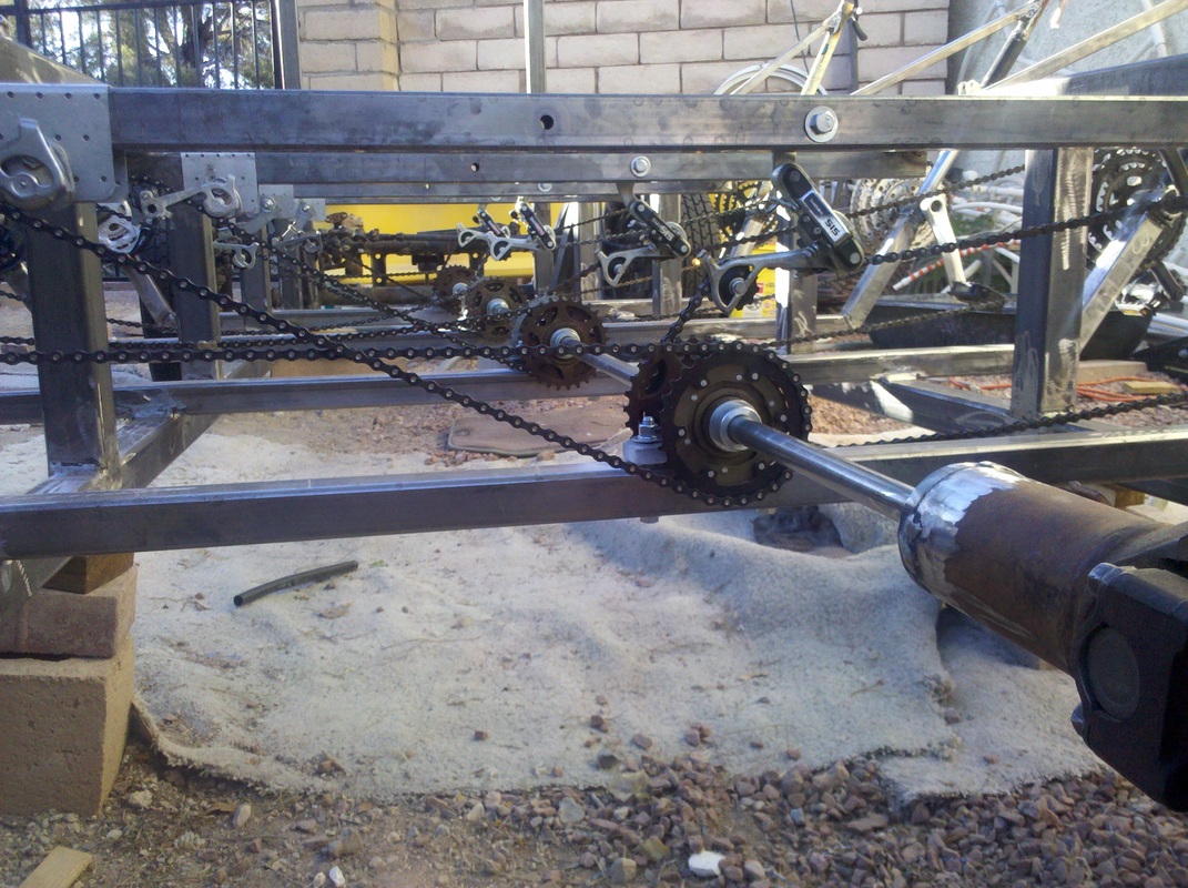
My favorite construction pic!
This might be the most challenging part. I got lots of help blogging with the members on the Atomic Zombies website. This drive system is a variant of the one published there in their trike plans, trying to minimize the machining required for a custom system..
Sprockets (freewheel hubs) & tools
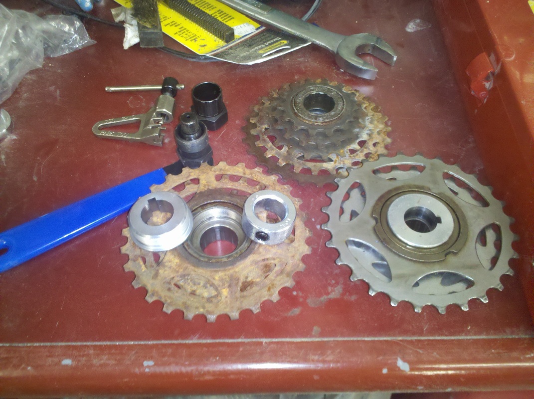
I'm not a big bike mechanic type. But as I understand it, there are two or three major types of freewheel hubs, and they are not interchangeable. But someone on the AZ site pointed out some commercially available adapters that made it an easy choice for me: Shimano type.
When mounted on a bicycle, the hubs have an adapter screwed into them that accommodate the bike axle and bearing set. We want to take that old adapter off so we can put another one on to fit the 3/4" driveline. I used a freewheel hub removal tool to get it off (the nut-looking thing in the pic above the crank removal wrench with the blue handle). They are really on there, so you will really need one. Park tool makes most bike tools, available at bike shops and internet. The top hub shows the old bike adapter still in the hub. The lower-left hub has the adapter removed, with the desirable adapter (note the 3/16" square keyway cut into the adapter) and a collar on it (all available from Staton, Inc.). The lower right hub shows the new adapter installed. It screws right in.
Most bike builders state that you shouldn't mess with used parts, but as seen in the picture I tried to recycle as much as possible from my Craigs List bikes. The one on the lower right is a brand new Shimano freewheel hub: Walmart.com: $9.00.
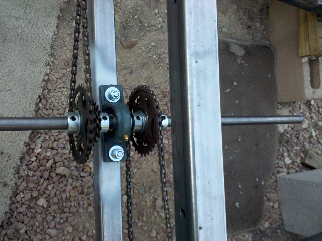
Freewheel hubs mounting
The top pic is a view of a crossmember with a pillowblock bearing, with the drive shaft and adaptered hubs slid on the shaft. The center hole is 3/4" diameter. Just right for our 3/4" cold-rolled drive shaft. It's gotta be cold-rolled; more expensive, but hot rolled isn't true; more egg-shaped and the adapter tolerance is such it won't fit. Note how I've dropped a key into the slot on the drive shaft (more on that below) in preparation to slide it into the keyway on the adapter. This keeps the hub from spinning on the driveshaft. I also slide the collars up against both sides of the hub and tighten their set screws to keep the key from coming out and the freewheel from wandering up and down the shaft while pedaling.
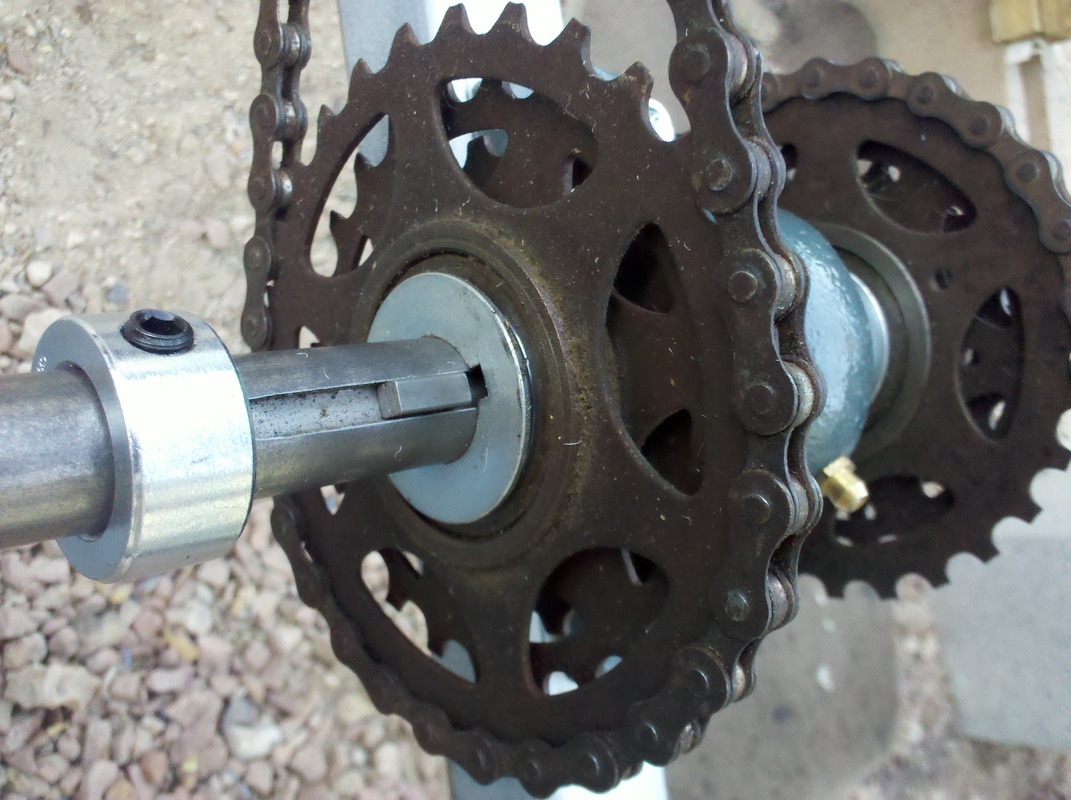
Completed freewheel hub and sprocket assembly
This pic shows the completed assembly.
Driveshaft keyway
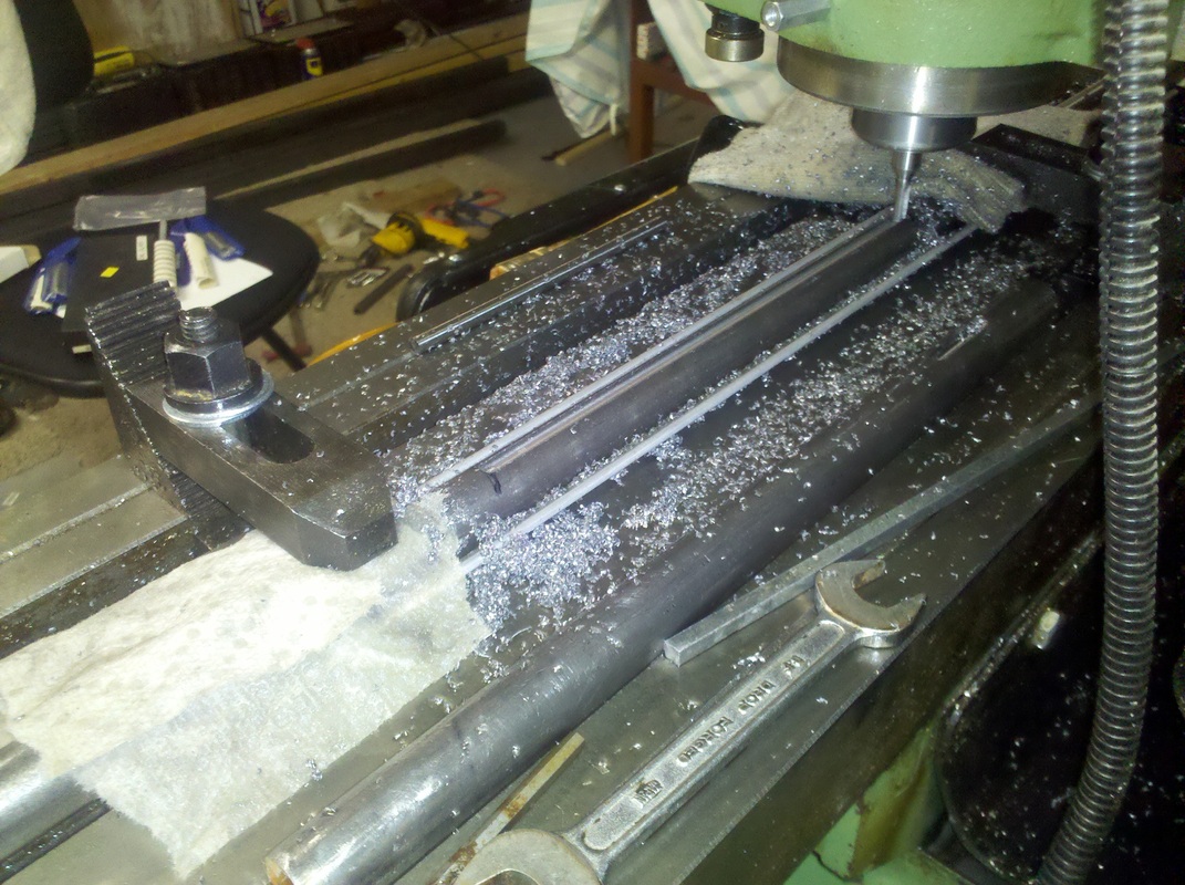
Regarding that keyway in the driveshaft, I think some of the Atomic Zombie trike builders buy cold-rolled 3/4" round stock from McMaster-Carr with the keyway precut in them. But not in a 10 foot length. I wasn't able to find a supplier, so I cut my own (I happen to own a vertical milling machine) on a blank piece of stock. Any machine shop could do it.
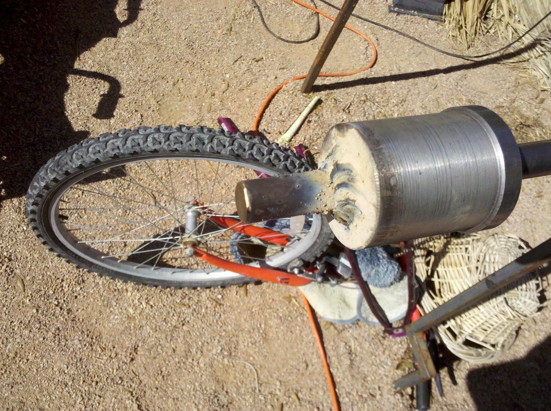
This photo is of my machine doing the job.
This photo is of my machine doing the job.
Adapting to the Camaro rear end
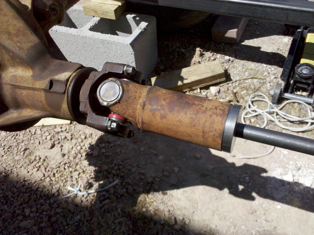
How to connect the 3/4" driveshaft to the rear end? Left is the assembled adapter. The Camaro driveshaft has been cut about 8" in front of the rear universal joint on the differential of the rear axle. The inside diameter of the driveline is a little smaller than 2 1/2".
Note: the yoke of the drive shaft coming out of the differential is actually pointed slightly upward, because the engine in the Camaro is higher than the rear end, so GM builds them that way. I thought that I would have to make some wedges to insert between the frame and rear axle to tilt it down to align better with the driveline. However, My buddy Les pointed me to SO-CAL Southern California speed shops. This seems to be an issue when hot rod builders use stock rear ends, and they already make wedges just for this purpose. I got two 7 degree wedges and installed them. I liked using the Camaro rear universal joint because it allows for a little rear end misalignment, and is more forgiving of my sloppy engineering...
Note: the yoke of the drive shaft coming out of the differential is actually pointed slightly upward, because the engine in the Camaro is higher than the rear end, so GM builds them that way. I thought that I would have to make some wedges to insert between the frame and rear axle to tilt it down to align better with the driveline. However, My buddy Les pointed me to SO-CAL Southern California speed shops. This seems to be an issue when hot rod builders use stock rear ends, and they already make wedges just for this purpose. I got two 7 degree wedges and installed them. I liked using the Camaro rear universal joint because it allows for a little rear end misalignment, and is more forgiving of my sloppy engineering...
Driveline adapter
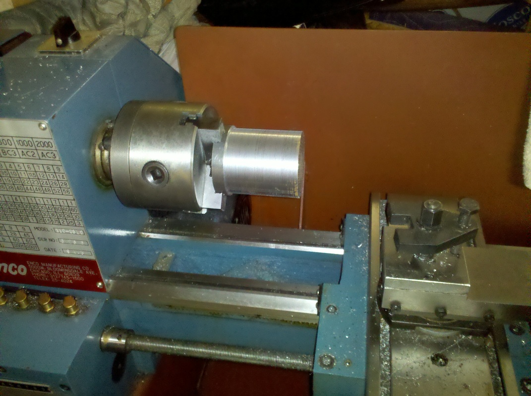
I took a short piece of 2 1/2" cold rolled round stock and turned it down on my metal lathe so it just fit snugly into the cut off driveline. Note that I left a shoulder on it so it wouldn't slide all the way through the Camaro driveline.
Driveline adapter drilling
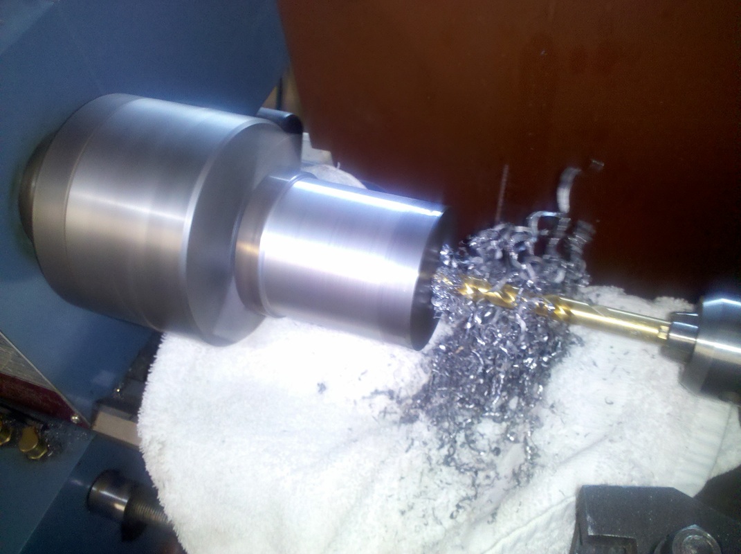
I then drilled a 3/4" hole through it for the driveline to slide through.
Driveline adapter welded
I then welded the adapter onto the driveline. I'm not a machinist (or a metalworker for that matter (o:) but I for some reason chose to weld it rather than drill and pin or bolt it. If doing again, I might do it differently. How much torque does 8 people pedaling provide?
I then inserted it into the Camaro driveline and welded it in.
I then inserted it into the Camaro driveline and welded it in.
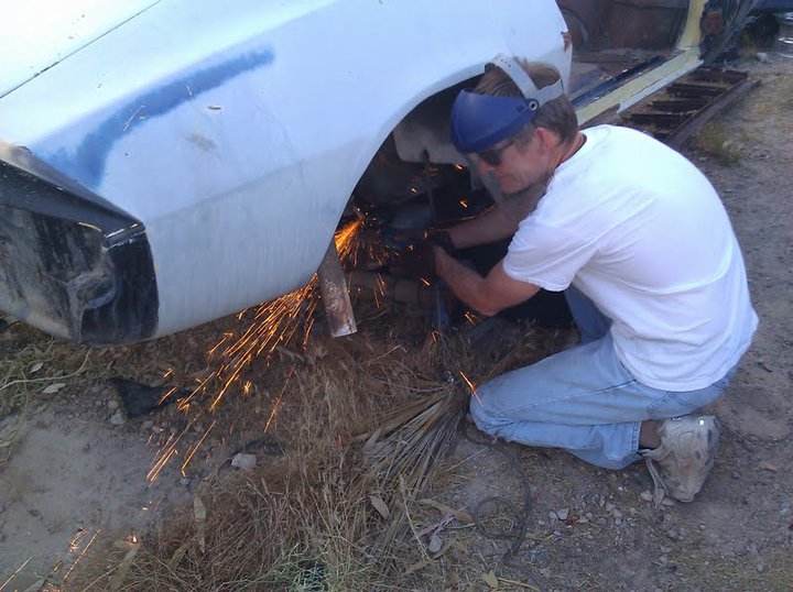
Yours truly, getting the rear end from Dale's ole' Camaro
